The Main Causes for and Protection Measures Against Optical Module Failures
Nov. 04, 2022
An optical module is a typically hot-pluggable optical transceiver used in high-bandwidth data communications applications. Optical modules typically have an electrical interface on the side that connects to the inside of the system and an optical interface on the side that connects to the outside world through a fiber optic cable.
The form factor and electrical interface are often specified by an interested group using a multi-source agreement (MSA). Optical modules can either plug into a front panel socket or an onboard socket. Sometimes the optical module is replaced by an electrical interface module that implements either an active or passive electrical connection to the outside world. A large industry supports the manufacturing and use of optical modules.
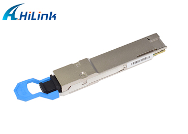
Hilink 400G-QSFP-DD DR4 Optical Module
What Are the Main Causes for and Protection Measures Against Optical Module Failures?
Optical modules must be operated in a standardized manner. Any non-standard operation may result in implicit damage or even permanent failure.
Main Causes for Optical Module Failures
The main causes of optical module failures are optical modules' performance deterioration due to ESD damages and optical links' unavailability incurred by optical bore contamination and damage. The possible causes of optical bore contamination and damage are as follows:
The optical bore is exposed to the environment and contaminated by dust.
The end face of the fiber connector is contaminated.
The end face of the fiber connector with a pigtail is improperly used. For example, the end face is scratched.
A poor-quality fiber connector is used.
Two main approaches are available to effectively prevent optical module failures: ESD prevention and physical protection.
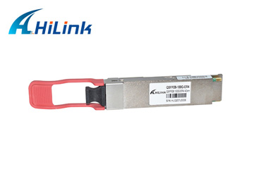
100G 40KM QSFP28 ER4
ESD Prevention
ESD damage deteriorates the performance of optical components or even causes optical component failures. In addition, it is difficult to detect optical components with ESD damage. If an optical component fails due to ESD damage, this failed optical component is hard to locate within a short time.
Operation instructions
1. When you transport optical modules, ensure that they are in ESD packages, and do not take them out unless necessary or place them at random.
2. Before touching an optical module, wear an ESD wrist strap or ESD gloves. Take full ESD measures when installing it.
3. Ensure that a device is properly grounded before you test or use it.
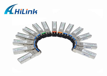
Dual Fiber 155m 4.25g SFP Transceivers
Physical Protection
Lasers and thermoelectric coolers (TECs) inside optical modules can be easily broken or disconnected after collisions. Therefore, physical protections are required during optical module transportation and usage.
Use a dedicated cotton swab to gently rub the stain on an optical bore. A non-dedicated cotton swab may cause damage to the optical bore. If the cotton swab is used with excessive force, the metal in the cotton swab may scratch the ceramic end face.
Tests on installation and removal of an optical module are based on manual operations, and so are the push force and pull force. Therefore, do not use tools to install or remove an optical module.
Operation instructions
1. Handle optical modules gently and protect them from falling.
2. When installing an optical module, push it gently by hand. When removing an optical module, unlatch it first. Never use any metal tools during installation and removal.
3. Use a dedicated cotton swab to clean an optical bore and do not insert any metal object into it.
For further technical information talk with our specialist or visit our website https://www.hilinktech.com. We can help you to identify the best solution for your application.


